21-04-21
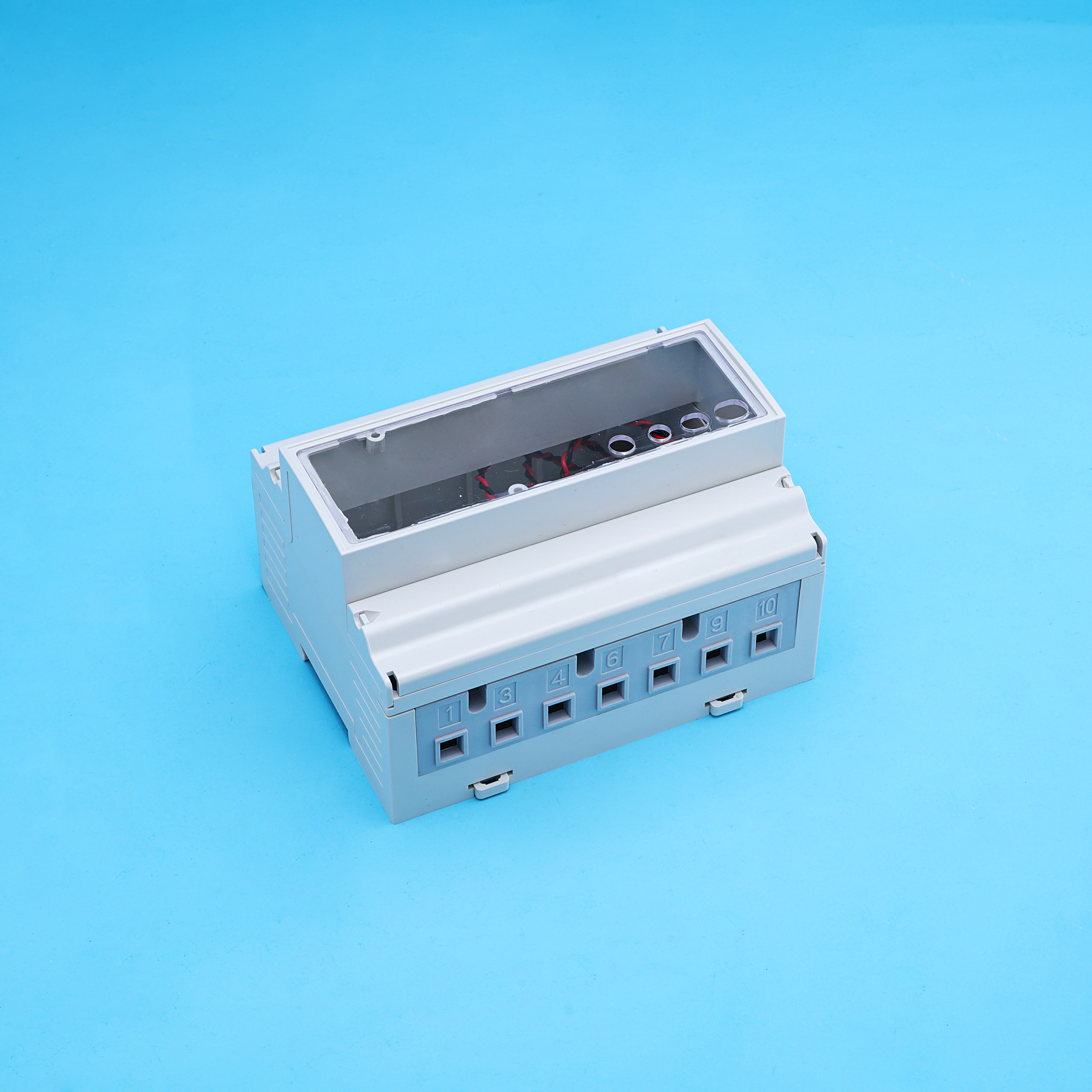
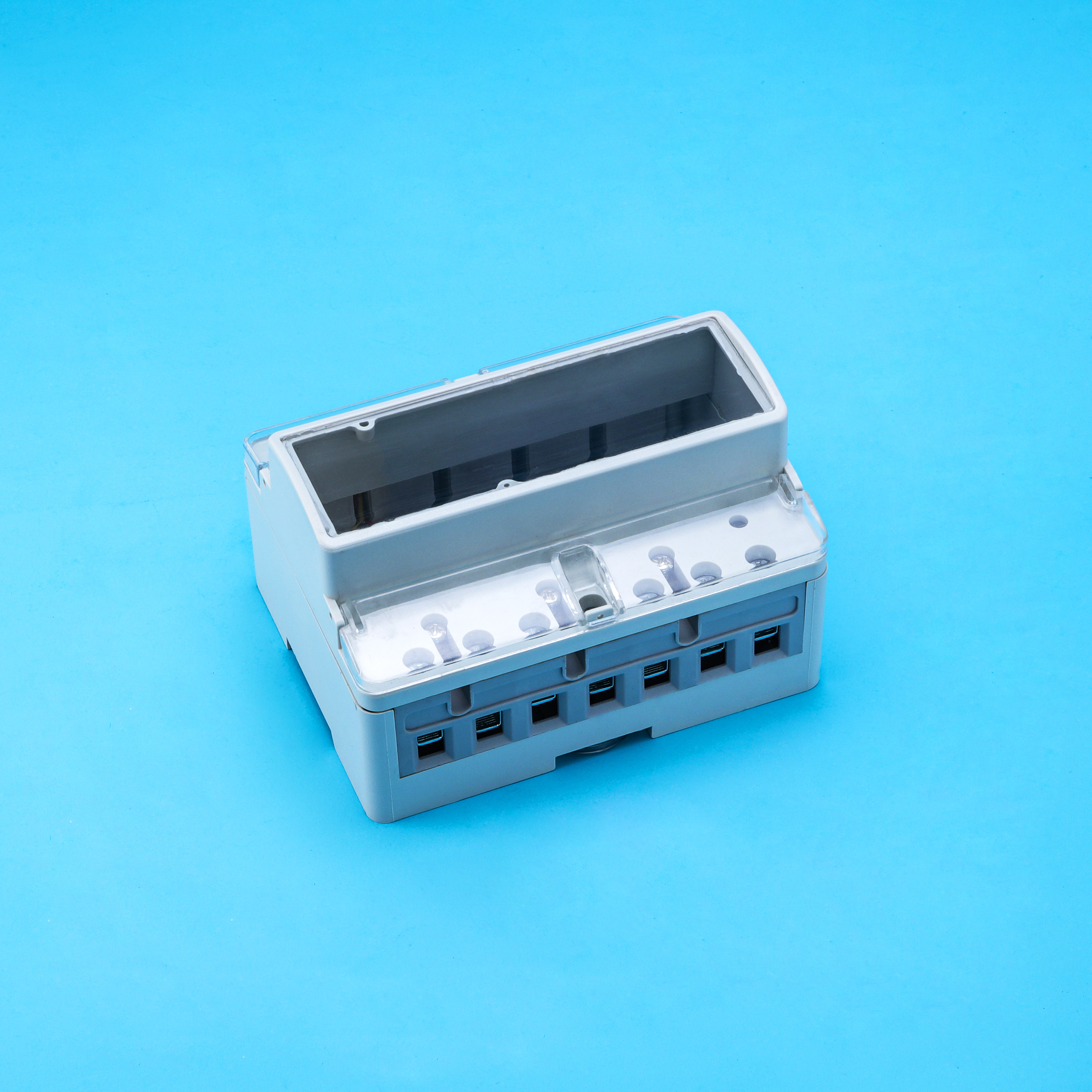
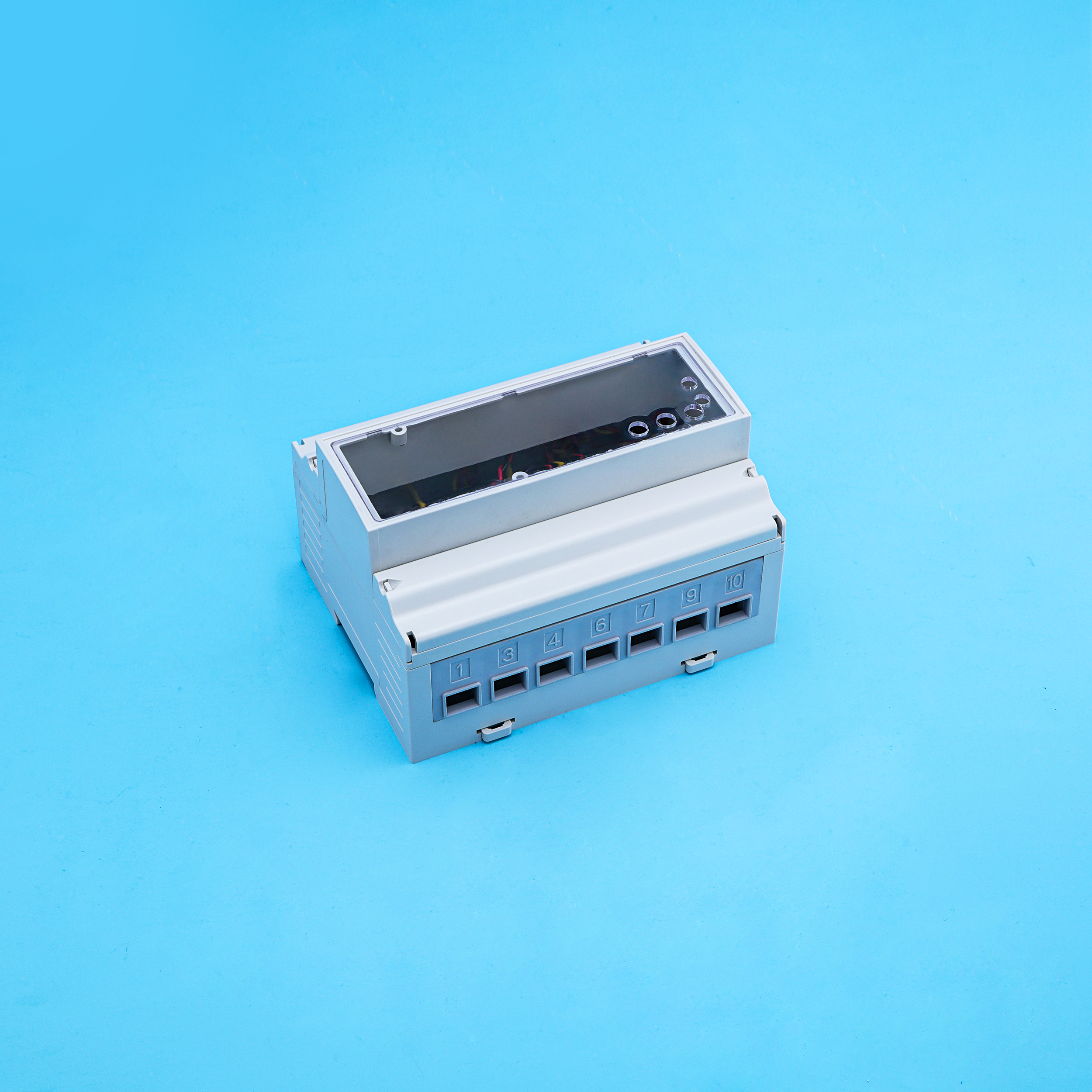
Performance requirements for payment meters with load switching on payment meters in standard IEC62055-31-2005
The two most relevant standards which apply to latching relay application are IEC61810-1 and IEC62055-31, IEC61810-1 apply to electromechanical elementary relays, this standard defines the normal function requirement and safty requirement for application, and IEC62055-31 defines the requirements to overcurrent ,short circult, fault current making capability etc. Following content list the main performance requirements for payment meters with load switching (latching relays) on prepayment meters in standard IEC62055-31.
C.1Load switching capabilities
Payment meters with load switching category UC2, UC3 or UC4 shall have the following
properties:
a) capable of making and breaking negligible currents of specified values;
b) capable of making, breaking and carrying rated currents of specified values;
c) capable of making into fault currents with specified value and under specified conditions;
d) capable of carrying short-circuit currents of specified value for a specified time period and
under specified conditions;
e) not required to provide safety isolation properties in the open contact position. These are
requirements for the installation mains isolation switch;
f) not required to break overload currents or short-circuit currents. These are requirements
for fuses and circuit breakers that are normally used to protect the installation.
A summary of test currents for utilisation categories UC2, UC3 and UC4 is given in Table C.1.
Table C.1 – Summary of test currents for UC2, UC3 and UC4
|
Test clause |
UC2 |
UC3 |
UC4 |
|
|
C.5 |
Fault current making capability |
2.5kA |
3kA |
4.5kA |
|
C.6 |
Short-circuit current carrying capacity testing 1 |
4.5kA |
6kA |
10kA |
|
C.6 |
Short-circuit current carrying capacity testing 2 |
2.5kA |
3kA |
4.5kA |
NOTE 2: Where the payment meter load switching capability is also used as part of the main circuit protection or isolation at the customer’s premises, then such additional requirements may be specified through reference to other specifications or standards.
C.2 Normal operation
The load switch shall be operable by the payment meter to interrupt the supply to the load
circuit when available credit expires.
The load switch shall be operable by the payment meter to restore the supply to the load circuit when available credit is replenished, but only under manual control; i.e. by pushing a button or by manually entering a token.
If the payment meter is programmed with other functions that also operate the load switch,then these other functions shall be disabled for the purpose of this test.
The test is carried out under the following conditions:
●payment meter in normal operating condition;
●load a small amount of available credit, so that the load switch restores the supply to the
load circuit;
●supply voltage at, or just above, the lowest value of the rated operating voltage range;
●current in the load circuit atIc and PF = 1,0;
Wait until the available credit expires and check for compliance with the following
requirements:
●the load switch shall interrupt the supply to the load circuit;
●the load switch shall operate on the first attempt;
●there shall be no evidence of sticking of the contacts;
●there shall be no change in any of the memory registers in the payment meter, except for
those that are expected to change.
Repeat the test 3 times.
Where a load switch has a mechanical actuating lever for manually closing or opening the
contacts, then perform each test when the lever is held in the following positions:
●when pushing the lever in the direction for closing of the contacts, then hold the lever at
the nearest point where the load switch contacts have just made contact;
●by inspection, select the nearest point to where the contacts are placed under the greatest
pressure during the closing operation;
●where the lever is in its normal resting position after the contacts have closed.
C.3 Electrical endurance
The test shall be carried out on a new sample under the following conditions:
●payment meter in normal operating condition;
●room temperature at reference conditions;
●1 mlength cable with current carrying capacity ofIc;
●supply voltage atUc;
●load current atIc and PF = 1,0;
●number of operating cycles equal to 5 000, with 10 s make time and 20 s break time.
Repeat the test using the same sample, but with the following changes:
●load current atIc and PF = 0,5 inductive.
●During and after the test the following requirements shall be met:
●the load switch shall show no signs of malfunction, sticking of contacts or reluctance
To latch;
●the contacts shall open on the first attempt;
●after the test it shall meet the requirements of C.7: test for minimum switched current;
●after the test it shall meet the requirements of 7.3 and its subclauses: test for power
consumption;
●after the test it shall meet the requirements of C.8: test for dielectric strength;
●when the payment meter is returned to normal operating conditions, it shall operate
correctly and there shall be no change in any of the memory registers, except for those
that are expected to change.
NOTE 1 One operating cycle of the load switch is one make followed by one break action.
NOTE 2 For the purpose of this test, the payment meter manufacturer may provide an external means, which allows for the opening and closing of the load switch to be under the control of the test equipment.
C.4 Line to load voltage surge withstand
The payment meter shall be able to withstand simulated lightning induced common mode
voltage surges as might be expected in a typical domestic installation, while the load switch
contacts are in the open position.
The test is only applicable to a payment meter in which the neutral line is also switched.
All current carrying phase and neutral input terminals are grouped and connected together;
and all current carrying phase and neutral output terminals are grouped and connected
together. All other terminals are connected to a safety ground reference.
Perform the test in accordance with IEC 61000-4-5under the following conditions:
●with load switch contacts in open position;
●payment meter in the non-operating mode;
●between the group of input terminals and the group of output terminals;
●ambient temperature at reference conditions;
●relative humidity at 40 % to 60 %;
●atmospheric pressure at 80 kPa to 106 kPa;
●cable length between surge generator and payment meter at1 m;
●open circuit voltage of generator at 20 kV (1,2/50 μs);
●prospective short circuit current of250 Apeak;
●generator source impedance of 80 ;
●5 positive and 5 negative impulses;
●repetition rate not faster than 1 impulse per minute;
During and after the test the following requirements shall be met:
●it is permitted for flashover and disruptive discharge to occur during the test;
●there shall be no permanent damage to any part of the payment meter;
●when the payment meter is returned to normal operating conditions, it shall operate
correctly and there shall be no change in any of the memory registers
NOTE 1
In certain networks lightning arrestors are only fitted differentially between the live and neutral lines.Lightning conditions are thus able to induce common mode voltage impulses in such a network on the live and neutral lines relative to earth. If the load switch contacts are in the open position under such conditions, then the impulse voltage will attempt to find a discharge path though any circuit that is connected across the open contacts to the load-side circuit, thus possibly causing damage to internal circuitry of the payment meter.
NOTE 2
This test is specifically designed for the case where there is internal electrical coupling of circuits between the input and output terminals of the payment meter when the load switch contacts are in the open condition.
C.5 Fault current making capacity
The payment meter shall be capable of making into simulated fault currents as given in this
Clause.
Perform the test on a new payment meter sample under the following conditions:
●climatic conditions at reference values;
●payment meter in the normal operating condition;
●voltage source atUc;
●3 pre-fusing operating cycles atIc and PF = 1,0 at 10 s intervals;
●prospective test current at 2,5 kA r.m.s. for utilisation category UC2;
●prospective test current at 3 kA r.m.s. for utilisation category UC3;
●prospective test current at 4,5 kA r.m.s. for utilisation category UC4;
●power factor of test current shall be inductive in accordance with Table 16 of IEC 61008-1;
●frequency at reference value;
●current tolerance +5 % –0 %;
●voltage tolerance +5 % –5 %;
●power factor tolerance +0,00 –0,05.
NOTE 1 One pre-fusing operating cycle is to maintain the switch contacts in the closed condition for 5 s, then to maintain the switch contacts in the open condition for 5S
Cause the payment meter to close the load switch contacts into the above prospective test
current and to remain in the closed position.
The test current shall be maintained to flow up to the first zero point crossing of the current, at
which point, the test equipment shall disconnect the voltage source.
Repeat the test 3 times on the same sample with a minimum delay of 1 min between each
test.
Plot a graph of the voltage and the test current waveform during each test and verify that the
test was executed as is required.
During and after the test the following requirements shall be met:
●contacts shall open on the first attempt after each make cycle;
●the load switch shall show no signs of malfunction, sticking or welding of contacts or
reluctance to latch;
●after the test it shall meet the requirements of Clause C.7: test for minimum switched current; ●after the test it shall meet the requirements of 7.3 and its subclauses: test for power consumption; ●after the test it shall meet the requirements of Clause C.8: test for dielectric strength;
●when the payment meter is returned to normal operating conditions, it shall operate
correctly and there shall be no change in any of the memory registers, except for those
that are expected to change.
NOTE 2 One operating cycle of the load switch is one make followed by one break action.
NOTE 3 It is recognised that there is significant statistical variance in the result of this test, but a more exact method is under consideration for a future revision of the standard
NOTE 4 Standard r.m.s. current breaking capacity values for residual current devices are given in5.3.10of IEC 61008-1 as 3 kA, 4,5 kA, 6 kA, 10 kA and 20 kA, which represent the fault current levels that the load switch of a payment meter is expected to make. The first two values are chosen for utilisation categories UC3 and UC4 respectively as representing the short-circuit current sourcing capacities at the load connection socket outlet points of wired premises where payment meters are commonly installed. Further categories may be created in future for higher current values. The values given for UC2 correspond to a special category, applicable only to certain countries where large quantities of prepayment meters are installed, which are rated to these levels of fault current withstand.
NOTE 5 The aim of the test is to check for welding of contacts caused by contact bounce at the point of closure into the test current. TheI2tlet-through energy is not an essential part of this evaluation at present and is thus constrained to a value that amounts to less than would be expected from protection devices of either a fuse type or circuit breaker type normally used in the distribution board of the wired premises under short-circuit conditions.
NOTE 6 Further test requirements for withstand ofI2tlet-through energy at various values of overload current are under consideration for a future revision of this part of IEC 62055. The values of overload currents under consideration are: 3x, 5x, 10x, 20x and 30xIcat PF = 0,8 and shall be co-ordinated with the maximum time delays expected from network protection devices at these current values.
NOTE 7 It is recommended that the plotted graph of the voltage and test current waveform be attached to the test report for future reference
NOTE 8 It is not permitted to allow the load switch to be activated under the control of the external test equipment, because it could possibly negate special techniques that the payment meter application process may employ, such as zero point switching. The load switch contacts thus have to be caused to close under the direct control of the payment meter itself.
C.6 Short-circuit current carrying capacity
The payment meter shall withstand simulated short-circuit currents as may be experienced
under short-circuit conditions in a payment meter installation
Test 1 shall be carried out on a new payment meter sample under the following conditions:
●climatic conditions at reference values;
●series connection of a voltage source, the payment meter under test, load to produce the required test current and a test switch;
●payment meter in the normal operating condition;
●3 pre-fusing operating cycles atIc and PF =1,0 at 10 s intervals;
●load switch contacts in the closed position;
●voltage source atUc;
●prospective test current at 4,5 kA r.m.s. for utilization category UC2;
●prospective test current at 6 kA r.m.s. for utilization category UC3;
●prospective test current at 10 kA r.m.s. for utilization category UC4;
●power factor of test current shall be inductive in accordance with Table 16 of IEC 61008-1;
●test switch closing at zero voltage crossover;
NOTE 1
One pre-fusing operating cycle is to maintain the switch contacts in the closed condition for 5 s, then to maintain the switch contacts in the open condition for 5 s.
●test switch opening at the first subsequent zero voltage crossover, thus remaining in theclosed position for one half cycle of the supply voltage;
●frequency at reference value;
●current tolerance +5 % –0 %;
●voltage tolerance +5 % –5 %;
●power factor tolerance +0,00 –0,05.
Repeat the test 3 times on the same sample with an interval of at least 1 min between each
test.Plot a graph of the voltage and the test current waveform during each test and verify that the
test was executed as is required
During and after the test the following requirements shall be met: it is permissible that the contacts may weld or burn away; the surroundings of the payment meter shall not be endangered;
protection against indirect contact shall remain assured;
Test 2 shall be carried out on a new sample under the following conditions:
the same conditions as for Test 1 shall apply, except that the prospective test current shall
be 2,5 kA r.m.s. for utilisation category UC2, 3 kA r.m.s. for utilisation category UC3 and
4,5 kA r.m.s. for utilisation category UC4
During and after the test the following requirements shall be met:
●the load switch shall show no signs of malfunction, sticking or welding of contacts or
reluctance to latch;
●contacts shall open on the first attempt
●after the test it shall meet the requirements of Clause C.7: test for minimum switched
current; after the test it shall meet the requirements of 7.3 and its subclauses: test for power
consumption;
●after the test it shall meet the requirements of Clause C.8: test for dielectric strength;
●when the payment meter is returned to normal operating conditions, it shall operate
correctly and there shall be no change in any of the memory registers, except for those
that are expected to change.
NOTE 2 :One operating cycle of the load switch is one make followed by one break action
NOTE 3 : If Test 1 is passed and the requirements for Test 2 are also met, then Test 2 need not be performed
NOTE 4
Standard r.m.s. current breaking capacity values for residual current devices are given in5.3.10of IEC 61008-1 as 3 kA, 4,5 kA, 6 kA, 10 kA and 20 kA, which represent the short-circuit current levels that the load switch of a payment meter is expected to carry. For Test 1, the third and fourth values are chosen for utilization categories UC3 and UC4 respectively as representing the short-circuit current sourcing capacities at the network supply point to customer installations where payment meters are commonly installed. Further categories may be created in future for higher current values. For Test 2, the first two values are chosen for utilisation categories UC3 and UC4 as representing the short-circuit current sourcing capacities at the load connection socket outlet points of wired premises where payment meters are commonly installed. The values given for UC2 correspond to a special category, applicable only to certain countries where large quantities of prepayment meters are installed, which are rated to these levels of fault current withstand
NOTE 5 :
The aim of Test 1 is to check that the safety of the installation to the user remains intact after experiencing a short-circuit condition directly on the payment meter output terminals. It is permissible for the payment meter to be non-functional after the test, but consideration shall be given to the risk of exposure to electric shock and the possibility of causing a fire.
NOTE 6: The aim of Test 2 is to check for welding of contacts caused by the contacts being forced open by magnetic forces due to the high value of fault current. TheI2tlet-through energy is not an essential part of this evaluation at present and is thus constrained to a value that amounts to less than would be expected from protection devices of either a fuse type or circuit breaker type normally used in the distribution board of wired premises under short-circuit conditions
NOTE 7 : It is recommended that the plotted graph of the voltage and test current waveform be attached to the test report for future reference
C.7 Minimum switched current
The test is carried out under the following conditions:
●payment meter in normal operating condition;
●test voltage atUc;
●test current at minimum switched current value and PF = 1,0;
●10 operating cycles at approximately 10 s closed and 20 s open
The following requirements shall be met:
●test current shall successfully conduct each time the contacts are in the closed position;
●test current shall successfully break each time the contacts are in the open position
NOTE 1 One operating cycle of the load switch is one make followed by one break action.
NOTE 2 For the purpose of this test, the payment meter manufacturer may provide an external means, which allows for the opening and closing of the load switch to be under the control of the test equipment.
C.8 Dielectric strength
It is not intended that the payment meter should meet the requirements for a mains isolator
switch of an installation, but when the load switch contacts are in the open condition, it shall
present a minimum level of isolation between the supply input and load output terminals.
In the case where the neutral line is not switched, only the current carrying input phase
terminals are grouped and connected together, and similarly the current carrying output phase
terminals are grouped and connected together. All other terminals are connected to a safety
ground reference.
In all other cases, the current carrying phase and neutral input terminals are grouped and
connected together, and the current carrying phase and neutral output terminals are grouped
and connected together. All other terminals are connected to a safety ground reference
Perform the test under the following conditions:
●with the load switch contacts in the open position;
●the payment meter in the non-operating condition;
●between input circuits grouped and output circuits grouped;
●impulse test voltage at 1 kV peak;
●a.c. test voltage at 2 kV r.m.s.
The impulse voltage test shall be carried out first and the a.c. voltage test afterwards
Apply the impulse voltage test as given in7.3.2of IEC 62052-11, but with the test voltage
level and between circuits as given above.
Apply the a.c. voltage test as given in 7.4 of IEC 62053-21, but with the test voltage level, and
between circuits as given above.
During and after the test the following requirements shall be met:
●there shall be no flash-over, disruptive discharge or puncture;
●when the payment meter is returned to normal operating conditions, it shall operate
correctly and there shall be no change in any of the memory registers.
NOTE Where the payment meter load switching capability is also used as part of the main circuit protection orisolation at the customer’s premises, then such additional requirements may be specified through reference to other specifications or standards.
C.9 Sequence of tests
The test sequence and sample plan given in Table C.2 is recommended
Table C.2 – Test sequence and sample plan
|
Test number |
Test clause |
Sample A |
Sample B |
Sample C |
Sample D |
|
|
1 |
C.2 |
Normal operation |
* |
|
|
|
|
2 |
C.3 |
Electrical endurance |
|
|
|
* |
|
3 |
C.4 |
Line to load voltage surge withstand |
* |
|
|
|
|
4 |
C.5 |
Fault current making capacity |
* |
|
|
|
|
5 |
C.6 |
Short-Circult current carrying capability test 1 |
|
* |
|
|
|
6 |
C.6 |
Short-Circult current carrying capability test 2 |
|
|
* |
|
|
7 |
C.7 |
Minimun switched current |
|
|
|
|
|
8 |
7.3 and 7.3.2 |
Power consumption in current circuits |
* |
* |
* |
* |
|
9 |
C.8 |
Dielectric strength |
* |
* |
* |
* |
|
NOTE1 The* in the table indicates that the particular test should be performed on the particular sample, but the sequence of the tests shall always follow the same order as the test number sequence, for example: sample A shall be subjuected to test numbers 1,3,4,7,8and 9. In that specific order. NOTE 2 tests 1 and 3 may alternatively be performed on any one of the samples B,C or D, Prior to performing the tests indicatd in the table. NOTE 3 Samples C might not be required, depending on the result of test 5 on sample B( See note3 of Clause C.6) |
||||||