21-04-21
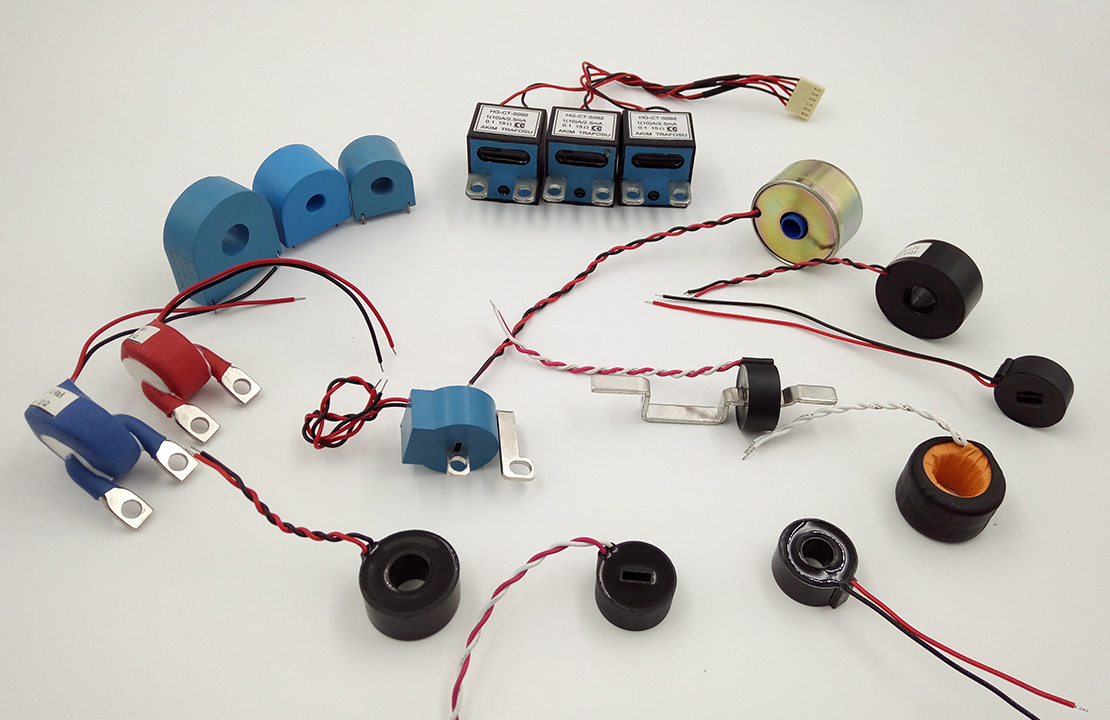
Current transformer for Electricity meters
We manufacture and supply many types of current transformer for Electric energy meter, the CT adopted high permeabilityMu metal and nanocrystalline core, with high accuracy class and good linear performance, conform to industrial standard JB/T10665-2016 for current transformer and international standard IEC60044 , In further, the CT will be inspected as per the standard JJG313-1994.
According to different installation method and performance requirements, the CTs will be classified as below:
CT for state grid electricity meter – S series
Straight-through current transformer - C series
CT with terminal – Y series
PCB mounting – P series
DC immunity CT –D series
Combined CT – Z series
Magnetic field immunity – T series
Power CT –G series
Transformer for detection and protection in instruments-G series
Technical requirements
Usage conditions
Working temperature -25℃~+75℃, humidity<90%(25℃);
No strong electromagnetic field in operating environment;
No gas, steam, chemical sediments, dust, and others harmful medium that might seriously affect the insulation of the CT;
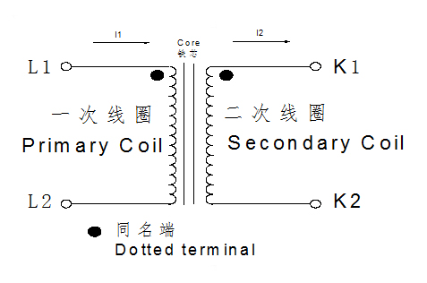
Rated voltage 500V, waveform of the power supply, sine wave waveform distortion coefficient: no more than 5%Schematic Diagram:
Ratio error
The error while testing current, it caused by different between actual current ratio and rated current ratio , it can be calculated in accordance with following formulas:
Current error=(KnIs—Ip)/Ip×100%
Kn: rated current ratio
Ip: actual primary current ( unit:A)
Is: actual secondary current while doing test by input Ip ( Unit: A)
Phase Error
It means the phase position difference between vector of primary current and vector of secondary current, Vector direction is subject to ideal current transformer whose phase error is zero. If secondary current vector is ahead of primary current vector, then phase error is positive number, its unit is usually sub-arc or arc.
The error ranges of current error and phase difference of transformers with different precision grades are as follows:
|
Class |
Ratio error(±%) In the percentage of (%)of input current |
Phase error(′) In the percentage of (%) of input current |
||||||
|
5%Ib |
20%Ib |
100%Ib |
120%Ib |
5%Ib |
20%Ib |
100%Ib |
120%Ib |
|
|
0.1 |
0.4 |
0.2 |
0.1 |
0.1 |
15 |
8 |
5 |
5 |
|
0.2 |
0.75 |
0.35 |
0.2 |
0.2 |
30 |
15 |
10 |
10 |
|
0.5 |
1.5 |
0.75 |
0.5 |
0.5 |
90 |
45 |
30 |
30 |
|
1.0 |
3.0 |
1.5 |
1.0 |
1.0 |
180 |
90 |
60 |
60 |
|
0.2S |
0.75 |
0.35 |
0.2 |
0.2 |
30 |
15 |
10 |
10 |
|
0.5s |
1.5 |
0.75 |
0.5 |
0.5 |
90 |
45 |
30 |
30 |
Insulation of the primary winding to the secondary winding and to the earth can withstand a voltage of 3KV with power frequency lasting for 1 minute.
Turn to turn insulation intensity
With opening circuit at the secondary winding, the turn-turn insulation of the CT won’t be damaged
when the primary winding pass rated current at rated frequency lasting for 1 minute.
Insulation strength
Primary winding to Secondary winding≥1000MΩ(DC500V)
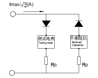
DC tolerance
As following figure, test the DC error of the CT after install the electricity meter,
0.1 Class CT will be controlled within±3.0% , 0.2 Class CT will be controlled within±6.0% ,